The L-unit

This is not about space-travel. I’m still fiddling with my mirrors.

In frustration of not getting anything remotely like sharp a peak in my spectra, I’ve been playing with my CNC in a slow move to replace plastic with aluminium.

I realize CNC mills aren’t as accessible to many as 3D-printers are, and good dog it certainly takes longer to manufacture a part in metal than in plastic. However, there’s a nice satisfaction in making a precision part in aluminium. It would be even more enjoyable if weren’t for manually creating the gcode, the breaking of expensive tools, and the anodizing post-process.

The OAP holders were already in aluminium, but recently they have been remade using the CNC, and are now more aligned than ever. I imagine being aligned is like being pregnant – either you are, or you aren’t. I guess you could argue my mirrors are poorly aligned, I hope no one is poorly pregnant.

Here’s my progress with the other mirrors:

DSC03667

The L-unit. The coin is for scale, but in case you haven’t seen a D-mark in a few years (it was the only coin I could find in the flat), the piece is 32×42 mm. The holes are 18 mm apart.

Continue reading

Mirror alignment. Don’t touch!

The new OAPs in protected aluminium have arrived. The rotating CCD-mount is complete. In other words, it’s time to play.

Figuring out how to align a plane mirror isn’t so bad. It’s still challenging to carry out though, not least because my flat is from 1936, two years before the 90° angle and the level floor-board was invented.

Figuring out how to align two off-axis parabolic mirrors (OAP)  was less easy, and I’m still not convinced I’ve done it right. But judge for yourself (and let me know if you find it wanting).

Continue reading

Picking (something) up where (one) left off

If you’re a recurrent guest you’ll have noticed that the activity has been low lately. It’s not my fault, it’s runs in my family to slow down and never complete anything. But no one want’s to become their parents, and I’m not an exception, so here we go:

The last thing I worked on was the cold tip. I couldn’t get it as cold as I wanted, so here’s what I’ve been on and off up to.

Continue reading

New toy day

Ok, so my CNC-mill actually arrived a few weeks ago, and I completed the control electronics last week (with quite a bit of delay, thanks to a set of burnt motor drivers).

In the meantime I’ve been trying to get my head around coordinate systems of the CNC-world, FreeCAD, GRBL, bCNC, gcode, climb-milling and conventional milling and possibly other things as well. I’ve tried to collect my thoughts here. It’s still a work in progress, but the CNC-mill is now up and running and I have the pictures to prove it:

Here’s the cold-tip for the CCD:

colptipcncd

coldtipcncdpcb

There are track-marks from the CNC. You can see them, but not feel them (and not just because you are sitting behind a screen), so I’m curious to see how it will respond when I anodise it black tomorrow.

The cold-tip is just one third of the entire rotating thermoelectrically cooled CCD-mount. The other two parts will be much less work. It’s basically just cutting two appropriately sized pieces of aluminium and drilling 13 holes. A task that would have been tedious and impossible (I’m still not good enough with my drill press that I can drill within the tolerances I want/need).


STM32F103 driving the TCD1304

Thanks to Zied Guermazi for showing me some time ago, that the STM32F103 “blue pill” can drive the TCD1304. Back then, he ported my UART-firmware for the STM32F401 to the STM32F103.

This week, while waiting for my small CNC mill to arrive (still waiting), I’ve been looking at GRBL. It was originally made for arduino, but fortunately there’s a port for the STM32F103. I first thought it was an STM32duino build, but it’s actually made with the standard peripherals library, so I became curious how USB was implemented.

After realizing that STMicro has a USB-library for the STM32F1xx, I quickly fell into the rabbit-hole.

There were two things that didn’t make me jump on Zied’s port back when he made it:

  1. The STM32F103 doesn’t have 32-bit timers, meaning the integration time is quite limited. Even with the slowest MCLK supported by the CCD it’s:
    tint (max) = 2¹⁶ / MCLK = 2¹⁶ / 800 kHz = 82 ms
  2. UART isn’t that convenient without the nucleo-board’s built-in USB->UART connection.

So I dug into the datasheet, reference manual and USB-library for the STM32F103. It took me some time to get USB working, especially how to send more than 64 bytes at a time.

I still haven’t solved the issue of the 32-bit timer. First I thought I could chain TIM3 and TIM1, and use TIM1’s capability for complementary outputs.

Using TIM1 in slave mode means timer’s counter is only increased when TIM3 overflows (that’s the whole point of chaining them together), however that also means the pulse-length is dependent on the period of TIM3. So I’ve put that idea on the shelf.

I left the 32-bit timer configuration intact, so if someone wants to implement the SH- and ICG-pulses manually through TIM1’s update interrupt, they can.

Back to what’s working:

The STM32F103 presents itself as a virtual com port, so the command-line interface, and the python-interface works out of the box. And here’s the first capture using the blue pill:

corkscrew-f103

Yes. It’s a cork-screw:

corkscrew-ccd

And here’s the whole setup:

blue-pill-tcd1304

The firmware runs the CCD at 800 kHz, so the timer violation warnings given by the pyCCDGUI shouldn’t be taken to seriously, just remember to keep SH and ICG smaller than 65536. I will probably add a radio-button or something in the pyCCDGUI to choose between the STM32F103 and STM32F40x.

Oh, and for good measure, here’s the pinout :

  • OS – PA1
  • ICG – PA10
  • SH – PB4
  • fM – PA15

Download the firmware over at tcd1304.wordpress.com

I will most likely make a TCD1304-shield for the blue pill with all the credit I’ve saved up over at dirtyPCBs from whenever people order one of my designs. Which side of the blue pill should the CCD be on?

Learning from mistakes – A new cold tip

3D-printing is not exactly fast, but at least my effective work-time is limited to drawing up the parts in openscad. Working in metal, however, is tedious and at times hard work too (I hate that).

So mistakes when making metal parts are expensive in time and money (but mostly time). I can’t remember when I figured out that 3D-printed drill-templates are a dog-send (I’m slow, so probably far too late).

But why stop at that.  I’ve invested in a small CNC-mill (Proxxon MF 70), so I’ll have to draw the parts anyway, and I might as well make 3D-printed dummies of the rotating heat-sink, before putting the CNC to work.

My 3D-printer is at work (in fact, it’s not my printer any longer, the school acquired it from after an amusing mistake where management claimed that the school possessed a 3D-printer), so printing will have to wait until Monday, but I can still show of the drawings:

heatsink-preview

From the top: CCD-PCB, cold-tip, peltier-element, rotating heat-sink, fixed heat-sink.

The top layers will be fixed relative to each, and hopefully look something like this:

rotating-parts

Notice the hole in the center of the bottom part. This is the rotational axis, and the hole will be threaded and used to secure the assembly to the part of the heat-sink fixed to the chassis of the spectrometer.

Hopefully printing dummies will help me catch any mistakes before they are permanently manifested in aluminium.

Someone beat me to it!

I’ve previously shared this link:

thepulsar.be

and if you didn’t check it out back then, you definitely should now. While I’ve been working on-again-off-again on this project for the past 3-4 years, this guy built a working diy raman spectrometer in few months time.

He makes it look so simple, that I can’t help feel slightly depressed.

But science is a collaboration (I tell myself, while eating consolation-ice-cream), and I’m excited to see that he has achieved clear spectre with a 5 mW laser, and a sensor smaller than the TCD1304.

I hope my setup will be as good, after all I ditched my first spectrograph design for something fancier (maybe I shouldn’t have done that, seeing how well this particular design performs in the hands of someone better than me). If not, there’s always more ice-cream.

Homework

I was hoping for something more exhilarating to report, but despite extensive and systematic efforts to align every single mirror in my setup (as systematic as someone untrained in optics can be), I’m once again stuck in a situation where the dispersed light hits the sensor as shown in the image to the right:

bitmap

As usual, I failed to read the stuff in the fine print. In Schieffer’s article they specifically mention that the CCD should be mounted on a rotary stage. I guess I now know why.

However, I can’t do that.

First, rotary stages are wicked expensive. Second, a rotary stage would interfere with my brilliant thermoelectric cooling setup. So it’s back to the drawing board, to find a solution that allows for efficient cooling and rotational freedom. I already have an idea, so that half the work done already, right?

Oh wait, there’s the sawing in metal, filing it pretty, anodising it black, tapping holes and probably stuff I forgot since last.

On the upside, I have a new and better peltier-element that I can make sure will fit in the new arrangement. The old peltier was running more or less at full capacity, which actually isn’t a good thing.

It’s been a while but if my memory serves me right, the cause was that my voltage regulator couldn’t sustain a drop of more than 1 V (with the cooling I could provide).

This time I’m not making that mistake. The new peltier is a TEC1-7108, which has a max-voltage of 8.4 V, but I will feed it 5 V straight from the ATX-PSU, so it should run cooler (haha) than the TEC1-03506. We’ll see how that will play out..

I’m not touching those mirrors ever again, but an unexpected problem arose. My grating holder needs more rotational freedom. That’s as simple as sawing off a few cm² of aluminium, I’m just to lazy to do right now (also I forgot to eat anything today).

btw here’s a small reward for reading about my frustrations. an .stl file with the locations of all the mirrors:

snapshot500

OAPs and mirrors.stl

Mirror alignment (II)

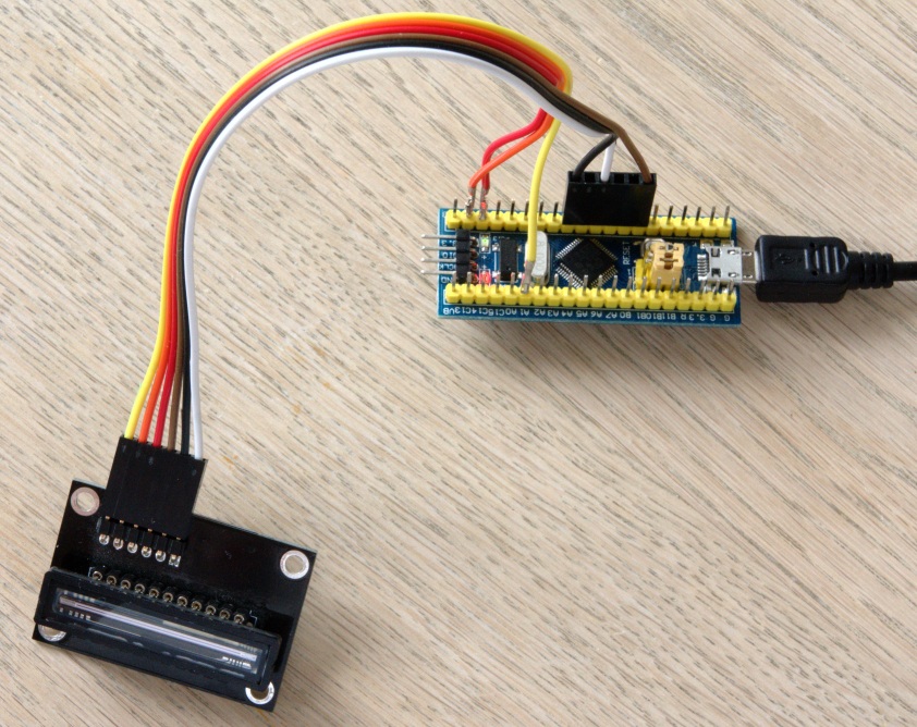
So I’ve been struggling to figure out how to align the mirrors in the spectrograph. The schematic looks like this:

schieffer-diagram

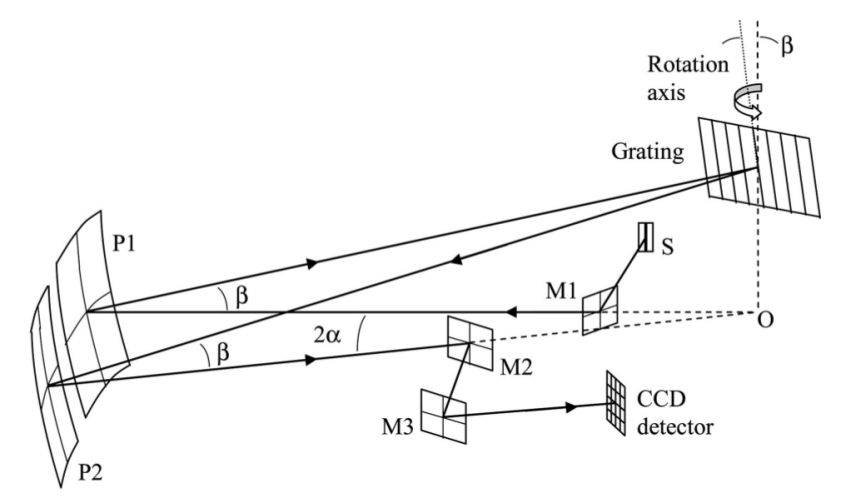
Schieffer et al. APPLIED OPTICS, Vol. 46, No. 16, p 3095-3101

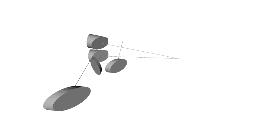
In my spectrograph this translates to:

1st-spectrograph-with-mirrors

Where P1 and P2 are 152.4 mm 90° off-axis parabolic mirrors (top right). M1, M2 and M3 are elliptical mirrors with an effective diameter of 25.4 mm (M1 is far left, M2 and M3 are in the center). The grating is not shown, but is positioned 152 mm “south” of P1 and P2 (at the end of the pencil line).

According to Schieffer the two parabolic mirrors should be arranged so that the slit is reflected onto itself. This is easier said than done (at least me for it was), as they have rotational freedom around their axis towards the grating, as well as rotational freedom along their off-axis focal point. So where do you start?

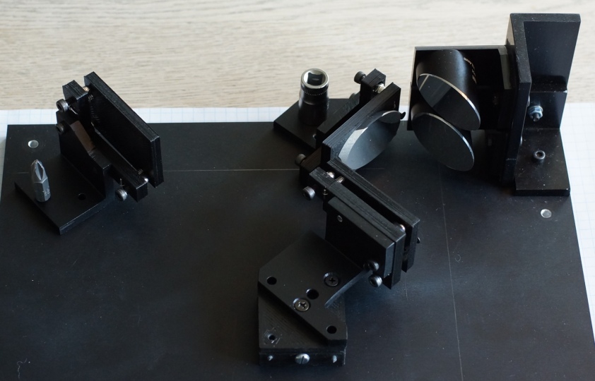
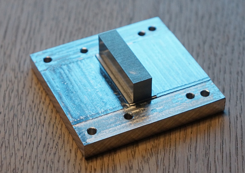
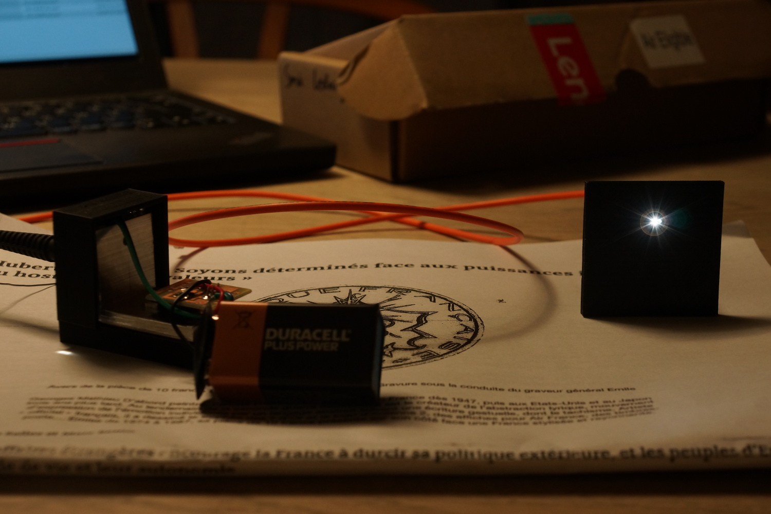
Well I started with removing M1 and M2.

A friend of mine who works at the Niels Bohr institute keeps telling me that 90° angles are my best friends, so I started with that: Having P1 and P2 oriented in horizontally along the aforementioned pencil line. P1 and P3 were then illuminated with an LED torch directed at the mirrors in a horizontal bee-line from the far end of my flat (that’s 7 m, I live in a studio appartment).

A block of aluminium with a cross to mark the height of the fiber port was placed at the focal point of P1, which was rotated until the focal point coincided with the cross. This was repeated for P2. So now I had something like this:

two-oaps-one-point

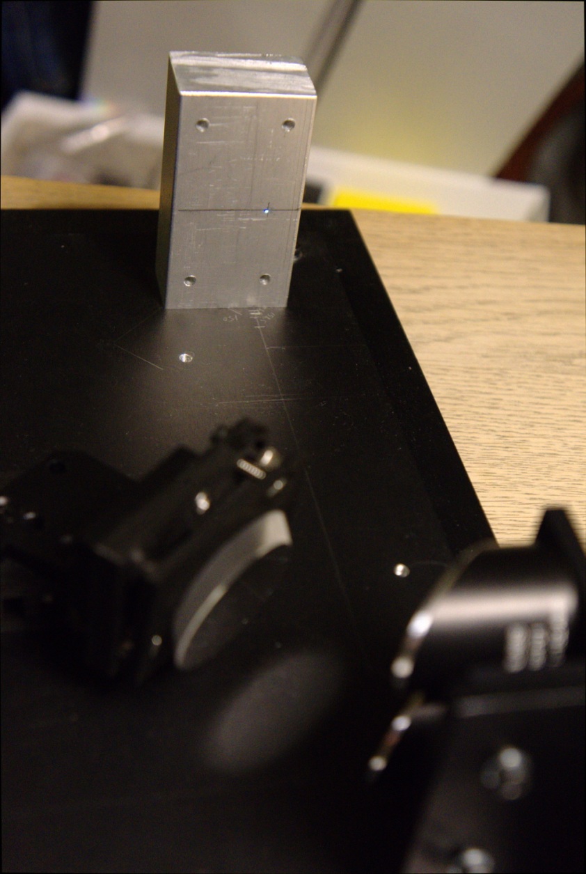
Two off-axis parabolic mirrors, one spot.

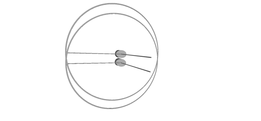
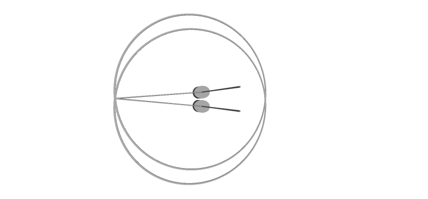
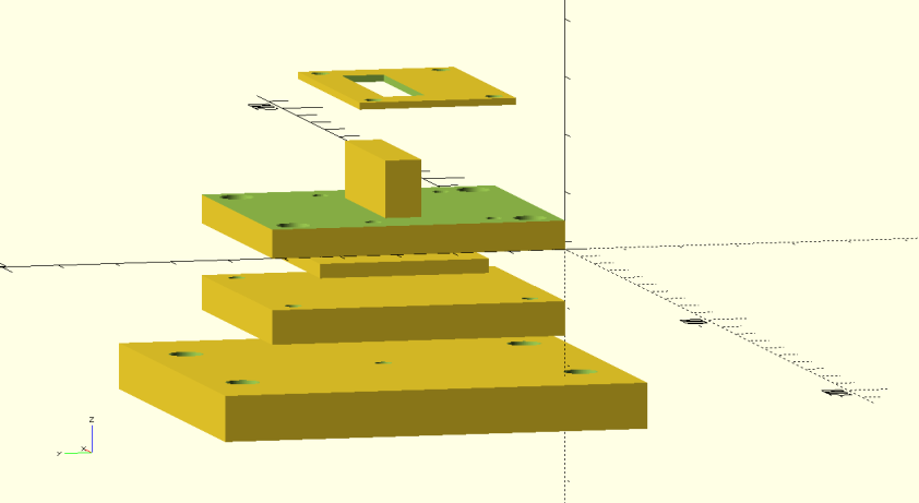
The two mirrors won’t stay parallel as they must be rotated so their principal axes (I’m not sure about the terminology here: the axes towards the grating) have an angle between them of 2α ie. 10.6° in my setup. This will introduce the first (small, I hope) error.

I’ve been trying to get my head around the magnitude of the error. I’m not an optical engineer, so I’ve made no attempts at further analysis than this:

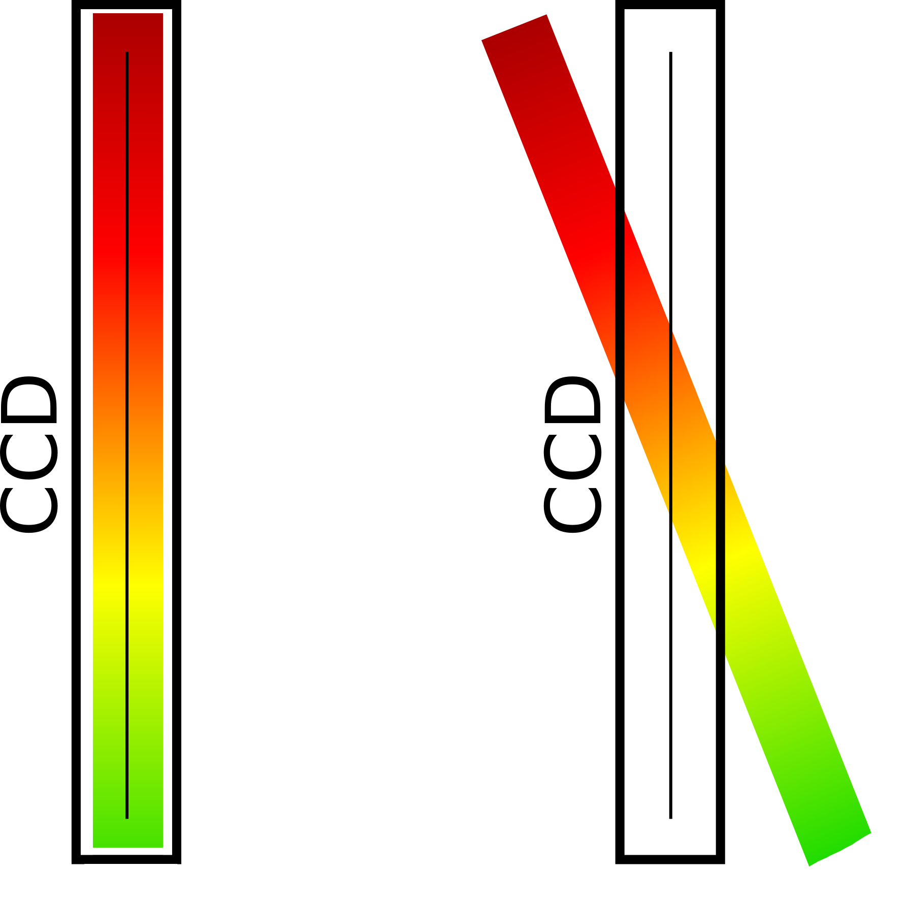
P1 and P2 before 1st adjustment. Ok, so it’s not superclear. In the center we have the two mirrors. The two lines ending in nothing are the mirrors axes towards the grating. The two lines the form the radii of the circles are the focal points of the mirrors. Btw the mirrors are 28 mm apart in the z-axis.

snapshot00

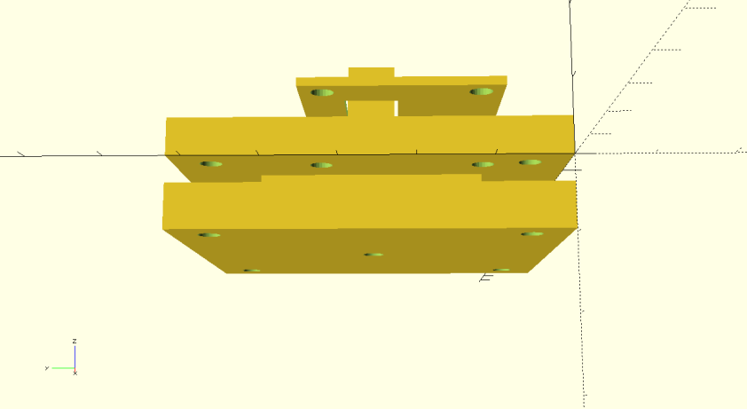
With the 1st adjustment show in the photo (two mirrors, one spot), the situation is now this:

snapshot101

So all that’s left is to bring the end points of the two axes towards the grating meet, ie. to rotate around the axes formerly defined by the focal points:

snapshot302

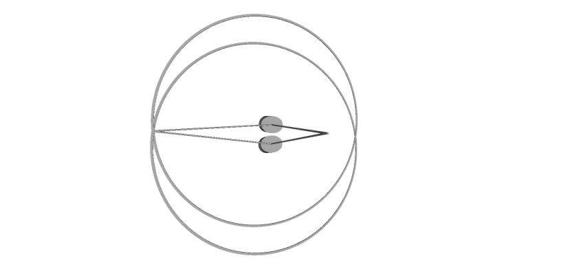
All is bliss, except that if you look at focal points from a different angle, there’s a small off-set:

snapshot403

hmm. Now that I’ve looked at it through the eyes of openscad, I guess there isn’t an issue, or it’s so small that it doesn’t help fretting over it. I could have sworn that on good old paper it wasn’t nothing.

I apologize for the long story (but I’m not erasing it), I’m only used to rotate molecules with my brain, not focal points and lines and circles.

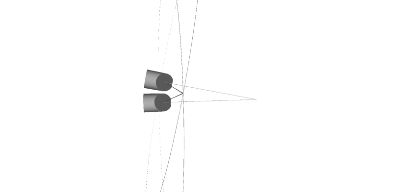
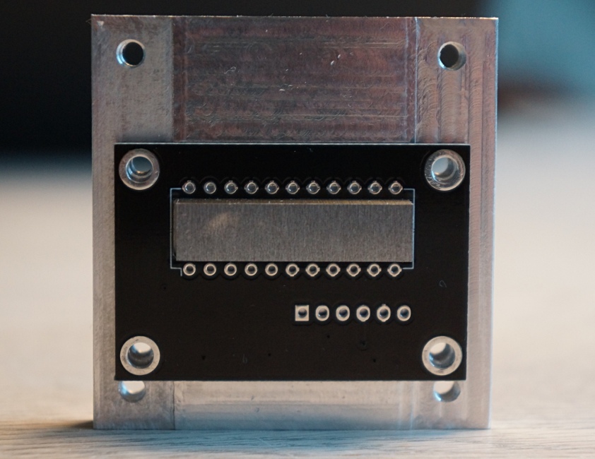
So now that that’s in order, we can procede to the next step: Installing and aligning M1 and the fiber port:

M1-fiber

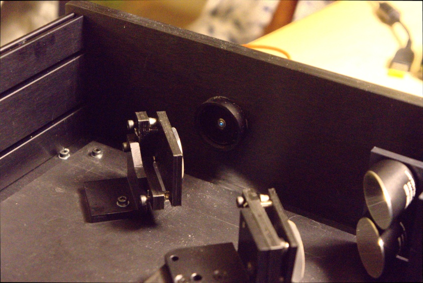
This was fairly straight-forward. I am a little concerned that I couldn’t manage getting a spot as well defined as on the aluminium target on the previous photograph.

With the fiber and M1 in place, the 2nd step for P1 and P2 was ready to be completed. Before 2nd aligment step it looks like this

DSC03560

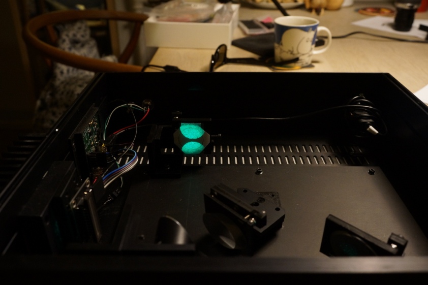
520 nm laser light from the fiber, collimated by the two off-axis parabolic mirrors and projected onto an ersatz-grating made out of paper.

Pretty cool right, but this next one has me really stoked:

DSC03563

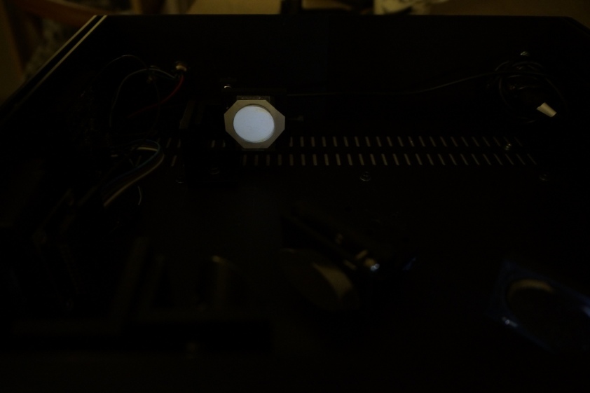
White light from a fiber, collimated by the two OAP’s and projected onto the same spot on the dummy-grating.

I never thought I would feel this way about a pale colourless circle. I’m in love. Notice how beautiful it is. It must be the most beautiful one in the whole world. Other peoples circles can just go home.

Ok, discrimination aside, the reason I’m so pleased with this, is that I’ve spent HOURS trying to get to this, but the two overlapping circles were just never very circular, leaving me with butterflyish patches of light. Btw pretty clever of nature to drug us with oxytocin, so we don’t throw away babies that were obviously riddled with beginner mistakes and just keep going until we finally get it right..

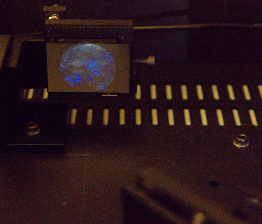
Ok, it’s obviously getting late for me. But here’s another beatiful circle. It’s my greasy fingers on a piece of glass.

DSC035661

I’ll post some more tmrw.

Not quite dead yet

It’s been quite a while since I’ve posted anything, so just to convince anyone reading along: the rumors of my death are greatly exaggerated

I’m still working on the project, albeit not very intensely, or regularly for that matter.

On paper, the Raman spectrometer is close to completion. In reality, aligning a few mirrors is not as straight forward as I imagined. I’m probably overthinking it. In fact I’m sure I am, and it keeps me from working (if I can come up with other excuses that sound better than too much TV, I’ll be sure to include them).

So far I’ve been trying to do the alignments using laser light (because it’s the easiest way to get light with enough intensity that I can actually see what I’m doing). However, I really need a line (to make sure the entire spectrum actually hits the sensor), and with laser light I of course only get a spot.

I realize the description above might be a bit under-explained, but it’s difficult to take pictures in very low light, to support what I’m trying to say. The sensor is positioned vertically relative to the spectrometer floor, so the Raman radiation should be dispersed vertically. However, when the parabolic mirrors are not properly aligned, the light arrives at the sensor at an angle. Something like this:

On the left: What I want. On the right: What I have.

So in line with my usual self, I’ve been trying to come up with a cheap and excellent way to couple lots of white light into a fiber. I’ll spare you the details of not-quite failed, but not-quite successful solutions and get right to the point:

The best I could do was simply to shove the fiber right up against a very bright, naked LED (an Osram Duris E5 4000K, if you must know). And it looks like this:

Not quite as intense a green 532 nm laser pointer pointed into the fiber, but not unacceptably far off.

The LED PSU is a very simple constant current source, someone on the internet Dan Goldwater had made a pencil diagram of:

One doesn’t need to populate all R2-R5, but it does leave some flexibility and since all the current flowing through the LED also flows through R2-R5 it’s nice/necessary to be able to spread out the heat on several resistors.

It ended up looking like this:

I made a whole bunch, because¹ I need drivers for cyanotype-UV-LED-exposure-boxes for my students, as well as a driver for a 340 nm LED that I’m still looking for a purpose for, and few other things.

[1] The real reason is that I was compelled to use the entire copper clad board. You see Denmark is a pig-country. We have 25 million living pigs (that’s 5 living pigs pr citizen ..and roughly 20 dead ones). And we use EVERYTHING from the pig. We’re like the eskimoes, only with pigs. And this cultural heritage sometimes seeps through to other aspects of our lives.